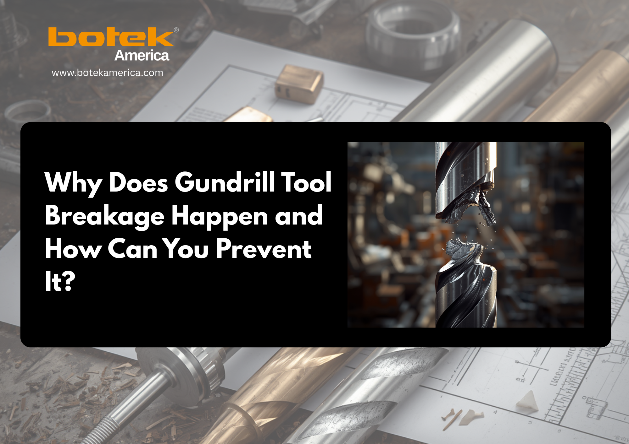
Gundrill tool breakage is rarely a random accident. In most deep hole drilling applications, a broken gundrill is the final result of a process problem that started earlier: chip jam, poor coolant pressure, low coolant flow rate, wrong feed rate, misalignment, runout, incorrect guide hole, or unmanaged tool wear.
The real cost is not only the broken carbide-tipped gundrill or solid carbide gundrill. It can also mean a scrapped workpiece, damaged bore, lost machine time, delayed production, and a difficult root cause analysis.
If your shop is dealing with repeat gundrill failure, speak with Botek America, a trusted Deep Hole Drilling System specialist before changing random parameters. A correct diagnosis can prevent repeated tool loss.
What Are the Early Warning Signs That a Gundrill Is About to Break?
The direct answer: watch the chips, spindle load, hole quality, sound, and tool wear before the tool fails.
A single-flute gundrill is a self-guiding tool, but it is not self-centering at entry. It depends on stable guidance, coolant delivery, chip evacuation, and correct cutting conditions. Before catastrophic failure, most tools show warning signs.
Look for these signals:
- Chips become long, stringy, blue, dark, or irregular.
- Coolant and chips stop flowing smoothly through the V-shaped flute.
- Spindle load or torque increases.
- Chatter, squealing, drill whip, or vibration appears.
- Hole diameter becomes oversize, undersize, tapered, or inconsistent.
- Surface finish becomes rough or burnished.
- The tool shows flank wear, margin wear, crater wear, guide pad wear, or cutting edge chipping.
These symptoms mean the cutting zone is no longer stable. Stop and inspect before the drill seizes or snaps.
Why Does Chip Jam Cause Gundrill Failure?
The direct answer: chip jam increases torsional load until the drill tip, brazed joint, shank, or driver fails.
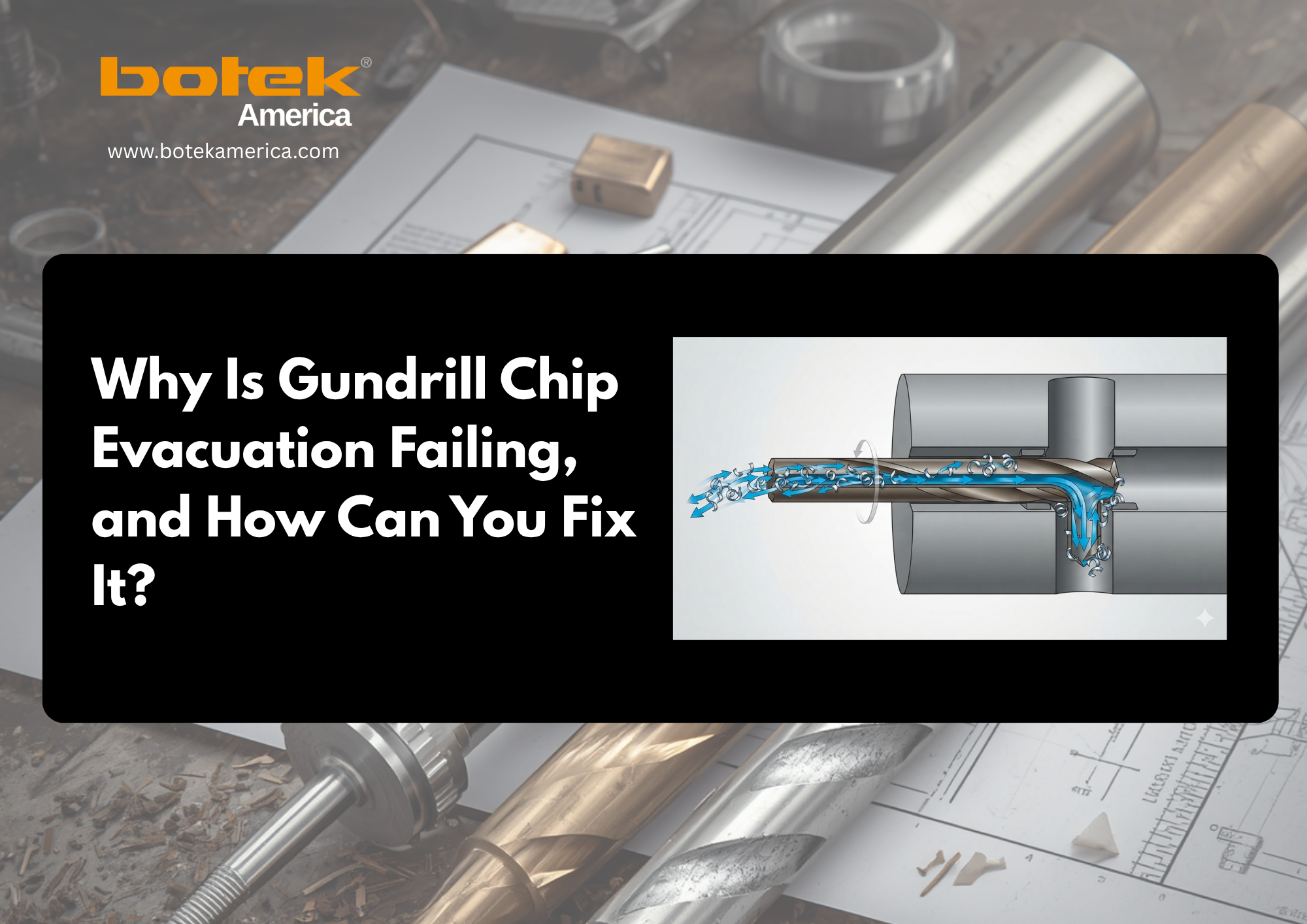
In gundrilling, coolant travels through the coolant hole and pushes chips back out through the external flute. If chip formation is poor, chips cannot evacuate cleanly. They pack inside the hole, recut against the drill body, increase friction, and create a torque spike.
This is one of the most common causes of gundrill tool breakage.
Chip packing usually happens because of:
- Insufficient coolant pressure or coolant volume.
- Clogged coolant hole or dirty coolant filtration.
- Wrong feed per revolution.
- Incorrect cutting speed.
- Poor nose grind geometry or chipbreaker geometry.
- Long-chipping materials such as stainless steel, titanium, low-carbon steel, Inconel, or ductile alloys.
- Excessive depth-to-diameter ratio, also called L/D ratio.
- Poor coolant viscosity or unsuitable deep-hole drilling oil/emulsion.
The solution is not always to reduce feed. If feed is too low, the tool may rub instead of cut, creating long chips and built-up edge. The better solution is to confirm chip shape, coolant flow, tool geometry, and feed rate together.
Is Coolant Pressure or Coolant Flow the Real Problem For Gundrill Tool Breakage?
The direct answer: both matter. Pressure moves coolant through resistance, but flow volume removes heat and chips.
Many shops only check the coolant pressure gauge. That is not enough. The gauge may show pressure, but the cutting edge may still be starved because of a blocked filter, restricted coolant passage, wrong coolant concentration, small coolant hole, poor pump capacity, or high hydraulic resistance at depth.
In gundrilling, coolant has three jobs:
- Cool the cutting edge and reduce thermal load.
- Lubricate the guide pads and drill periphery.
- Evacuate chips from the cutting zone through the flute.
A 2025 study on gun drill wear found that higher coolant pressure improved cooling stability, chip evacuation, chipping resistance, and tool wear behavior in deep drilling of 24CrMoV5-5 steel.
Before blaming the tool, check:
| Coolant Check | Why It Matters |
| Pressure at the machine | Needed to overcome hole depth and flow resistance |
| Coolant flow rate | Needed to carry chips out of the hole |
| Filter condition | Dirty filters reduce delivery and clog coolant holes |
| Coolant concentration | Poor concentration increases heat, wear, and built-up edge |
| Oil vs emulsion | Deep-hole drilling oil often improves lubrication |
| Coolant temperature | Excess heat reduces process stability |
| Tool coolant hole | Any blockage can cause immediate gundrill failure |
Can Wrong Speeds and Feeds Break a Gundrill?
The direct answer: yes. Incorrect speeds and feeds can overload the cutting edge or create poor chips that jam the flute.
If the feed rate is too high, chip load increases. This creates high cutting force, tool deflection, carbide tip breakage, and mechanical load on the drill tube and shank. It may also overload the guide pads and reduce hole straightness.
If feed is too low, the tool rubs. Rubbing creates heat, built-up edge, long chips, poor chip morphology, and premature tool wear. This can be just as dangerous as feeding too aggressively.
If spindle speed is too high, thermal load rises. If cutting speed is too low, chip formation may become unstable. The correct values depend on:
- Workpiece material.
- Hole diameter.
- Hole depth.
- L/D ratio.
- Carbide grade.
- Tool coating.
- Coolant pressure and flow.
- Machine rigidity.
- Toolholder rigidity.
The practical solution is to change one variable at a time. Do not adjust speed, feed, coolant, and geometry together, or you will lose the root cause.
How Do Misalignment, Runout, and Poor Guide Holes Cause Breakage?
The direct answer: a gundrill must enter straight. If entry guidance is wrong, the tool bends, rubs, walks, or breaks.
Unlike a short twist drill, a gundrill is long and slender. It needs a correct guide bushing, guide hole, or pilot hole to stabilize the entry condition. If the guide hole is too loose, shallow, misaligned, or off-center, the drill starts cutting under side load.
Common setup causes include:
- Excessive total indicated runout, or TIR.
- Poor spindle/workpiece concentricity.
- Weak workholding rigidity.
- Long unsupported tool length.
- Incorrect guide bushing clearance.
- Tool entering at full feed too early.
- Poor alignment between machine spindle and hole centerline.
- Exit condition causing tool whip or sudden breakthrough load.
The solution is to verify setup before production. Check TIR, guide hole tolerance, bushing clearance, toolholder rigidity, and workpiece rigidity. On a CNC lathe or machining center, entry control becomes even more important because the machine may not have the same support as a dedicated deep hole drilling machine.
When Is Tool Wear the Real Cause of Gundrill Failure?
The direct answer: tool wear becomes dangerous when it increases cutting force, heat, and chip instability.
A worn gundrill usually gives warning signs before it breaks. The hole finish gets worse. Size control becomes unstable. Chips change shape. Spindle load rises. The tool may show uneven wear, margin wear, flank wear, crater wear, guide pad wear, built-up edge, or cutting edge chipping.
The mistake is running the tool until it fails. A broken tool gives no usable tool life data. A worn tool does.
Inspect the drill head regularly:
- Is the cutting edge chipped?
- Are guide pads worn unevenly?
- Is the nose grind damaged?
- Is the margin polished or burned?
- Is the drill body rubbing inside the bore?
- Is the tool producing poor surface finish before failure?
The solution is preventive tool inspection and controlled tool regrinding. Regrinding must preserve correct nose grind geometry, chipbreaker form, and cutting edge condition. A poorly reground gundrill can cause chip control problems, poor roundness, poor cylindricity, centerline deviation, and short tool life.
Could the Tool Geometry Be Wrong for the Material?
The direct answer: yes. Wrong geometry can create long chips, high force, poor finish, and early breakage.
Tool geometry controls how the material cuts, breaks, and leaves the hole. The nose grind geometry affects chip formation, coolant behavior, cutting force, surface finish, hole straightness, and process stability.
Different materials behave differently:
- Aluminum may need geometry that prevents built-up edge.
- Stainless steel may need better chip control to avoid stringy chips.
- Titanium and nickel alloys need heat control and stable cutting.
- Hardened steels require edge strength and correct coolant delivery.
- Brass and free-machining materials may allow more stable chip breaking.
Do not use one geometry for every material. Match the drill head, coolant hole design, guide pads, and cutting data to the actual workpiece material.
What Is the Fastest Diagnostic Checklist After a Gundrill Breaks?
The direct answer: inspect the failure mode before changing cutting data.
Use this checklist before restarting production:
| Symptom | Likely Cause | First Corrective Action |
| Chips packed in hole | Chip jam, low flow, wrong feed | Check coolant pressure, flow, filter, and chip shape |
| Tip chipped | High feed, misalignment, hard spot | Check guide hole, entry feed, and material condition |
| Tool seized | Heat, poor lubrication, chip packing | Check coolant concentration, oil/emulsion, and coolant hole |
| Breakage at depth | Poor chip evacuation at high L/D ratio | Increase flow, inspect flute loading, verify chipbreaker geometry |
| Poor finish before failure | Tool wear, vibration, wrong geometry | Inspect wear pattern and toolholding |
| Hole wandered | Runout, bad guide bushing, poor support | Check TIR, concentricity, and workholding |
| Torque spike | Chip clogging or tool rubbing | Stop, clear hole, inspect drill body and chips |
This turns gundrill troubleshooting into a process instead of guesswork.
How Can Shops Prevent Gundrill Tool Breakage Before It Stops Production?
The direct answer: standardize the application before the first production run.
A stable gundrilling process needs more than a good tool. It needs the right system around the tool.
Before production, confirm:
- Correct carbide-tipped gundrill or solid carbide gundrill selection.
- Correct tool diameter, drill tube length, shank, and driver.
- Proper guide bushing or guide hole.
- Verified coolant pressure and coolant volume.
- Clean coolant filtration.
- Correct deep-hole drilling oil or emulsion.
- Material-specific speeds and feeds.
- Controlled entry feed and exit condition.
- Stable machine, toolholder, and workpiece rigidity.
- Operator monitoring of chips, sound, load, and finish.
- Scheduled inspection for premature tool wear.
If breakage continues, the issue may be application-specific. Send your tool diameter, hole depth, material, machine type, coolant details, current cutting data, failure photos, and chip samples to a gundrilling specialist.
What Is the Main Takeaway on Gundrill Tool Breakage?
Gundrill tool breakage is usually the final symptom of an unstable deep hole drilling process. The most common root causes are chip jam, poor chip evacuation, insufficient coolant pressure, low coolant flow rate, tool wear, wrong speeds and feeds, misalignment, runout, poor guide hole conditions, and incorrect tool geometry.
The fastest path to prevention is a structured diagnosis: inspect chips, coolant, setup, tool wear, geometry, and cutting data before restarting production.
Need help solving repeated gundrill failure
If you need help solving repeated gundrill failure, Contact botek America, your Gundrilling System partner, to review your application and identify whether the issue is chip evacuation, coolant delivery, tool geometry, alignment, or tool wear.