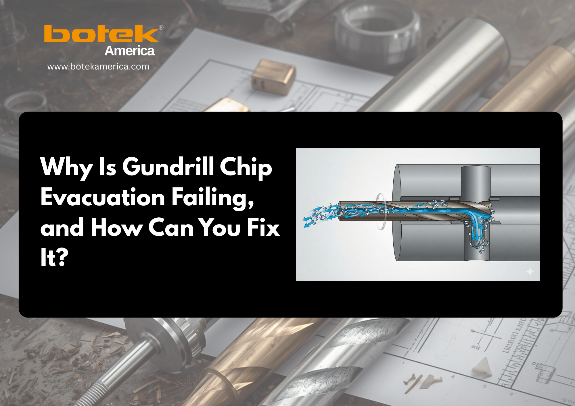
Poor gundrill chip evacuation comes from one of two conditions: the cutting edge is producing chips that cannot pass through the V-flute, or the coolant system cannot carry those chips out of the hole.
gundrill tool breakage. Stop the cycle when chip discharge becomes irregular, spindle load rises, or the tool begins to bind. This guide helps you isolate problems across chip formation, coolant flow, cutting data, tool geometry, filtration, and machine setup.
Need application-specific support? Consult an experienced Deep Hole Drilling Manufacturer specialist before changing multiple process variables.
What Does Poor Gundrill Chip Evacuation Look Like?
Watch the chips, coolant return, spindle load, and bore finish. Changes in these four areas appear before a complete blockage.
- Chips stop exiting continuously.
- Coolant return becomes weak or irregular.
- Long, stringy chips or chip nests appear.
- Spindle load or torque begins rising.
- The gundrill squeals, vibrates, or binds.
- The drill body or bore surface becomes scratched.
- Cutting-edge wear increases unexpectedly.
- Coolant or chips become unusually hot or discolored.
When should you stop the cycle?
Stop immediately if chip discharge disappears, torque spikes, or the drill binds. These symptoms indicate chip congestion around the carbide drill head or inside the flute channel. Early removal prevents cutting-edge chipping, brazed-joint damage, or catastrophic tool failure.
Why Do Chips Pack More Severely as the Hole Gets Deeper?
As the depth-to-diameter ratio increases, chips must travel farther through a narrow return path. Even a small loss of coolant volume or flute clearance causes chip packing. Understanding how gundrilling works is key: coolant travels through the driver, shank, coolant hole, and drill head, reaching the cutting zone and returning along the external V-flute while carrying chips toward the hole entrance.
- The chip-and-coolant return path becomes longer.
- Chips have more opportunities to overlap or bridge.
- Friction and heat increase.
- A damaged flute or rough bore creates more resistance.
- Small inconsistencies in chip morphology become serious restrictions.
Why can the setup work near the entrance but fail deeper in the bore?
The evacuation margin decreases with depth. A setup that moves chips near the entrance can repeatedly block farther down when pump output, flute clearance, or chip shape is only marginal. By contrast, BTA drilling evacuates chips through the drill tube internally by supplying coolant around the tube. Process selection depends on diameter, depth, machine configuration, and output requirements.
Is the Problem Coolant Pressure, Coolant Flow, or Both?
Check both pressure and volumetric flow. High pressure at the pump does not prove that sufficient coolant volume is reaching the cutting edge. Pressure supplies force; flow rate supplies the fluid needed to cool the tool and transport chips.
Which coolant-system restrictions should you check?
- A clogged coolant filter or incorrect filtration level
- Insufficient coolant-pump capacity
- Leakage around the toolholder or coolant seal
- A restricted spindle passage
- Blocked single-hole, dual-hole, or kidney-shaped coolant passages
- Incorrect coolant concentration or excessive viscosity
- A worn pump, relief valve, driver, or shank passage
What should you verify before changing cutting data?
- Coolant level, temperature, viscosity, and concentration
- Filter condition and pump output
- Spindle, holder, fitting, and seal leakage
- Coolant-hole obstruction
- Actual flow at the tool
- Coolant return and chip discharge during cutting
Why do tool diameter and coolant properties matter?
Small-diameter gundrills need higher pressure through smaller passages. Larger tools need more volumetric flow to transport a greater chip load. Coolant viscosity, lubricity, temperature, tool diameter, hole depth, and coolant-hole geometry all affect the requirement. Use the application data for the specific tool and machine rather than a universal pressure figure.
Are the Chips the Wrong Shape for the Flute?
Healthy chips should be short, consistent, and small enough to move freely through the flute. Long, stringy, nested, welded, or discolored chips require correction before drilling continues.
What does each abnormal chip condition indicate?
| Chip Condition | Likely Cause | First Corrective Action |
| Long or stringy | Feed does not activate the chip former | Verify feed per revolution |
| Nested or tangled | Poor chip control or restricted flute space | Inspect geometry and coolant flow |
| Blue or discolored | Excessive heat or coolant starvation | Check delivery and cutting speed |
| Irregular thickness | Edge damage, runout, or instability | Inspect carbide head and alignment |
| Welded material | Built-up edge or weak lubricity | Check coolant and cutting data |
Can increasing feed improve chip evacuation?
Sometimes. Reducing feed is not always the solution. In some materials, a controlled increase within the recommended range helps the chip-breaker geometry produce shorter chips. Reducing feed too far creates thin, stringy chips that block the flute. Change one variable at a time and record chip shape, spindle load, bore quality, and tool condition.
Could the Gundrill Be Causing the Flute Blockage?
Inspect the cutting edge, guide pads, coolant passages, and V-flute. Tool wear or incorrect regrinding disrupts both chip formation and coolant transport.
- Chipped or rounded cutting edges
- Built-up edge on the carbide drill head
- Incorrect chip-former, dub-off, or clearance geometry
- Damage inside the flute channel
- Blocked coolant holes
- Worn or damaged guide pads
- A cracked brazed joint or coating wear
When should the gundrill be reground or replaced?
Regrind when edge wear, chip formation, cutting load, or surface finish moves outside the proven process window. Regrinding must restore the original cutting geometry, not merely produce a sharp edge. Incorrect point geometry changes cutting forces and chip morphology, which directly affects evacuation. botek® America’s gundrill regrinding service restores original geometry using 5-axis CNC grinding at the Roselle, IL facility with short turnaround to maintain production continuity.
Could the Machine Setup Be Restricting Chip Evacuation?
Verify alignment, runout, support, guide-bushing condition, and seal integrity. Machine instability creates an evacuation problem even when coolant pressure appears adequate. For a full overview of how each machine variable interacts with the process, see the gundrilling process guide.
- Tool-to-spindle alignment and tool/workpiece runout
- Guide bushing wear and position
- Driver and toolholder compatibility
- Tool support during entry
- Spindle vibration and coolant sealing
- Bore-entry condition
Poor alignment forces the drill body against the bore wall. This reduces return space around the V-flute, restricts coolant flow, damages guide pads, and causes hole drift or scoring. The tool, coolant system, guide support, workholding, and cutting data must operate together for reliable chip evacuation.
Should You Use Peck Drilling to Clear a Gundrill Chip Jam?
Do not use peck drilling as the default correction. Gundrills are designed for continuous cutting with through-tool coolant and stable chip evacuation. A full retraction can allow chips to fall back into the bore; re-entry can chip the carbide edge or bind the tool.
Pecking does not correct insufficient coolant volume, clogged filters, poor chip shape, leakage, flute damage, tool wear, or incorrect cutting data. Use a controlled break-chip cycle only when the tool manufacturer or application engineer approves it.
What Is the Fastest Way to Diagnose Poor Chip Evacuation?
Match the visible symptom to the most probable cause, then follow a fixed sequence instead of changing speed, feed, and coolant settings simultaneously.
| Symptom | Probable Cause | First Check |
| Stops at repeatable depth | Low flow or restricted return | Actual coolant delivery |
| Sudden torque rise | Developing chip jam | Stop and inspect flute |
| Weak coolant stream | Filter, pump, seal, or restriction | Coolant system |
| Scored drill body | Recutting or alignment error | Discharge, support, runout |
| Built-up edge | Heat or insufficient lubricity | Coolant and cutting data |
| Finish worsens with depth | Packing, wear, or instability | Chips, guide pads, flute |
Which troubleshooting sequence should operators follow?
- Stop before the tool binds.
- Collect and inspect the chips.
- Inspect the drill head, guide pads, and flute.
- Confirm actual coolant flow.
- Check filtration, pump capacity, leakage, and restrictions.
- Confirm feed, speed, and tool geometry.
- Change one variable and run a controlled test.
- Document the results.
Where can operators review current coolant-safety guidance?
Coolant management also affects operator safety. OSHA’s Metalworking Fluids: Safety and Health Best Practices Manual explains how machining operations should evaluate exposure and use suitable engineering controls.
Avoid using an air wand to scatter coolant-covered chips unless the process has been assessed and controlled.
When Should You Contact an Application Engineer?
Request support when chip packing continues after verifying coolant delivery, tool condition, alignment, and recommended cutting data. Provide:
- Tool diameter, overall length, hole depth, and depth-to-diameter ratio
- Material grade and hardness
- Machine and coolant-system details
- Coolant type, pressure, and measured flow
- Cutting speed and feed per revolution
- Chip and tool-wear photographs
- Depth at which blockage begins
- Spindle-load or torque data
These details help determine whether the correction requires different cutting values, chip-former geometry, coolant-hole design, tool coating, or process selection.
How Can You Prevent the Next Gundrill Chip Jam?
Produce short chips, maintain verified coolant flow, preserve the original tool geometry, and respond to early warning signs. Poor chip evacuation is one of the primary drivers of shortened gundrill tool life and accelerated wear that reduces bore quality and production stability.
Effective chip evacuation is not controlled by pressure alone. It depends on the combined performance of the coolant pump, filtration system, cutting fluid, CNC machine, gundrill geometry, carbide head, guide pads, holder, and operating parameters. Pressure is one input among many.
If poor chip evacuation is reducing tool life, bore quality, or production stability, botek® America provides application-specific support from an experienced deep hole drilling team.
Contact botek® America’s engineering team to review your application, or explore our full range of Deep Hole Drilling Systems and gundrill tooling.