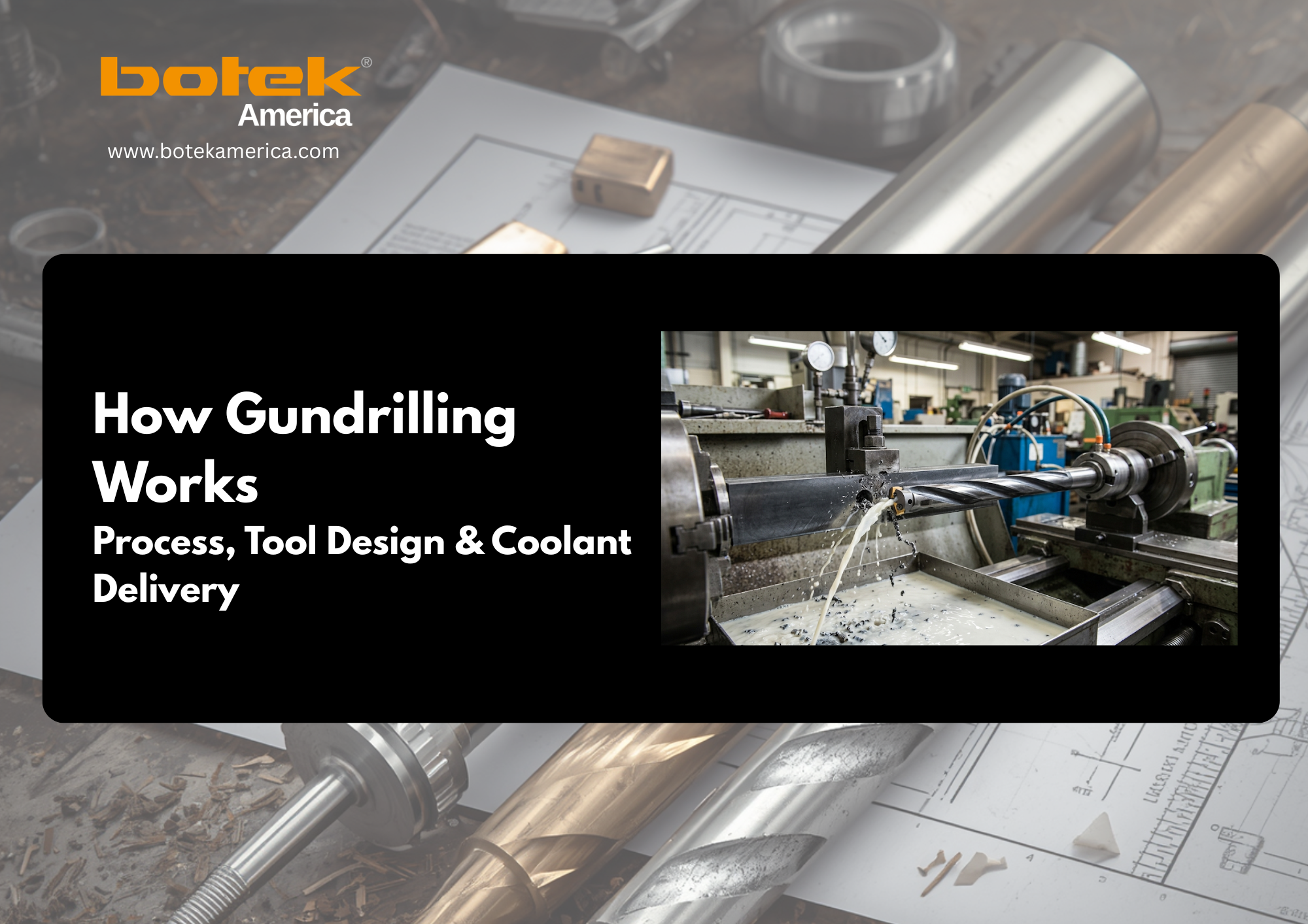
| Gundrilling produces deep, straight holes with tight tolerances by combining three things that only work together: a single-flute cutting head, an internal high-pressure coolant channel, and a V-shaped flute that sweeps chips backward out of the hole. Remove any one and the process fails. |
The deeper a hole gets, the harder chips are to remove, the more heat builds at the cutting edge, and the less control you have over tool deflection. Gundrilling solves this with a different tool geometry and a different chip-removal strategy, producing consistent diameter, tight straightness, and good surface finish at depth-to-diameter ratios of 100:1, 200:1, and, in optimized setups, 400:1.
The Problem Gundrilling Solves
Deep holes fail for one of three reasons: chip packing, heat buildup, or tool deflection. In a standard twist drill, all three get worse with depth. Chips travel back up the flute against gravity and rotation. That works at shallow depths. But by 10x to 15x the diameter, chips start to pack, generating friction and heat and causing the tool to wander. By 20x to 30x, a twist drill has essentially lost control of the hole.
Gundrilling solves all three problems at once with one design principle: separate the coolant delivery path from the chip evacuation path, and put both inside the tool.
Gundrill Anatomy
A single-flute gundrill has three components, and all three have to work together.
The cutting head is a solid carbide tip brazed to the drill tube, carrying one cutting edge instead of two. Alongside it sit two hardened guide pads that ride against the hole wall and keep the head centered throughout the depth, acting as a bearing surface that continuously corrects drift. A worn guide pad is the leading cause of hole drift in production gundrilling, so inspect them before every run. The head also carries the coolant port, a kidney-shaped or circular orifice that releases high-pressure coolant at the cutting zone.
The drill tube is the hollow body. Inside, high-pressure coolant travels from the spindle to the cutting head. Outside, a V-shaped flute runs the length of the shank, forming the chip evacuation channel between the tool and the hole wall. Because the flute removes material from the tube’s circumference, the cross-section occupies roughly three-quarters of a circle, which is why the system is sometimes called a three-quarter drill.
The driver connects the tube to the spindle, transferring rotational force and carrying a through-hole that seals the coolant feed as the tool turns.
How Coolant Delivery Works
In a twist drill, coolant runs down the outside of the tool and barely reaches the cutting zone at depth. In a gundrill, coolant is pressurized at the machine, travels through the driver and the hollow drill tube, and exits directly at the cutting edge. It arrives exactly where the heat is generated.
That pressurized flow does four things simultaneously: cools the cutting edge, lubricates the guide pads against the hole wall, pressurizes the chip path so chips sweep continuously out through the V-flute, and (in optimized processes) produces a light burnishing effect that improves surface finish.
Pressure requirements scale with hole diameter and depth. As a starting point:
| Hole Diameter | Coolant Pressure |
| Under 3 mm (0.12″) | 80–200 bar |
| 3–8 mm (0.12″–0.31″) | 60–120 bar |
| 8–20 mm (0.31″–0.79″) | 40–80 bar |
| Over 20 mm (0.79″+) | 30–60 bar |
Deeper holes need more pressure than shallow ones at the same diameter, since coolant has to carry chips the full length of the flute. Fluid type matters too: deep-hole drilling oil gives better lubrication for small diameters, titanium, stainless steel, and Inconel, while water-miscible emulsion works for larger diameters but needs a minimum 10–12% concentration. Below that, the lubricating film breaks down and guide pad wear accelerates. For a full breakdown of pressure and fluid selection by application, see botek® America’s gundrilling process guide.
How V-Flute Chip Evacuation Works
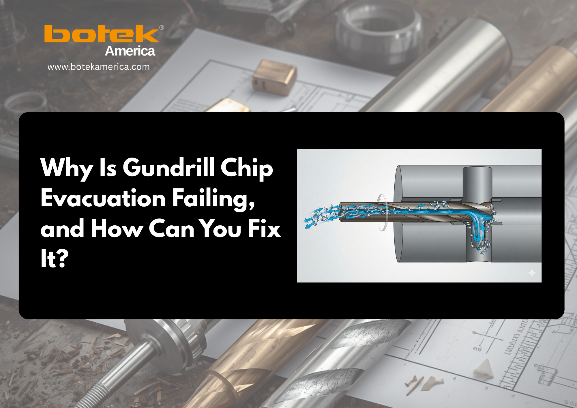
Coolant exits the cutting head at high pressure, picks up chips, and carries them backward through the V-flute to the hole entry. This is the reverse of a BTA drilling system, where chips travel internally through the drill tube instead. In gundrilling, coolant is internal and chips are external.
This gives two practical advantages: evacuation is continuous, so the hole rarely needs clearing mid-cycle, and chip form is visible at the exit point, so a developing blockage shows up before it becomes a problem.
| Why Chip Jams Cause Gundrill Breakage
About 80% of gundrill breakage starts with a chip jam. When chips pack in the V-flute, coolant flow drops, heat rises fast, and the tool seizes. The resulting torque spike breaks the drill tube. A sudden pressure drop mid-cycle is almost always a jam forming; stopping immediately is the best save. |
Keeping the flute clear also depends on filtering coolant to 25 microns or better, since recirculated abrasive particles accelerate both flute and cutting-edge wear. Check concentration with a refractometer, not by eye.
The Process, Step by Step
- Entry and guidance. The gundrill enters through a drill bushing (dedicated machine) or a pre-drilled pilot hole (CNC center), stabilizing the tool before the guide pads engage. Without this, the tool walks regardless of quality.
- Coolant pressurization. High-pressure coolant begins flowing as the tool enters, lubricating the edge and guide pads while pressurizing the chip path.
- Chip evacuation. The single cutting edge removes material; chips are swept back through the V-flute immediately and continuously.
- Depth advancement. The tool advances at a controlled feed rate while the guide pads self-pilot it on center. The drill isn’t fighting the hole. It’s guided by it.
- Breakthrough and retraction. The feed rate drops near breakthrough to control exit quality, coolant flushes remaining chips, and the tool retracts for inspection.
Tolerances and Surface Finish
| Parameter | Typical Capability |
| Hole diameter range | 0.5–51.2 mm (0.020″–2.016″) |
| Depth-to-diameter ratio | Up to 400:1 dedicated machine; 20–40:1 on CNC center |
| Surface finish (Ra) | 0.4–1.6 µm |
| Hole straightness | ±0.1 mm per 100 mm of depth (typical) |
| Roundness | IT6–IT7 achievable in optimized conditions |
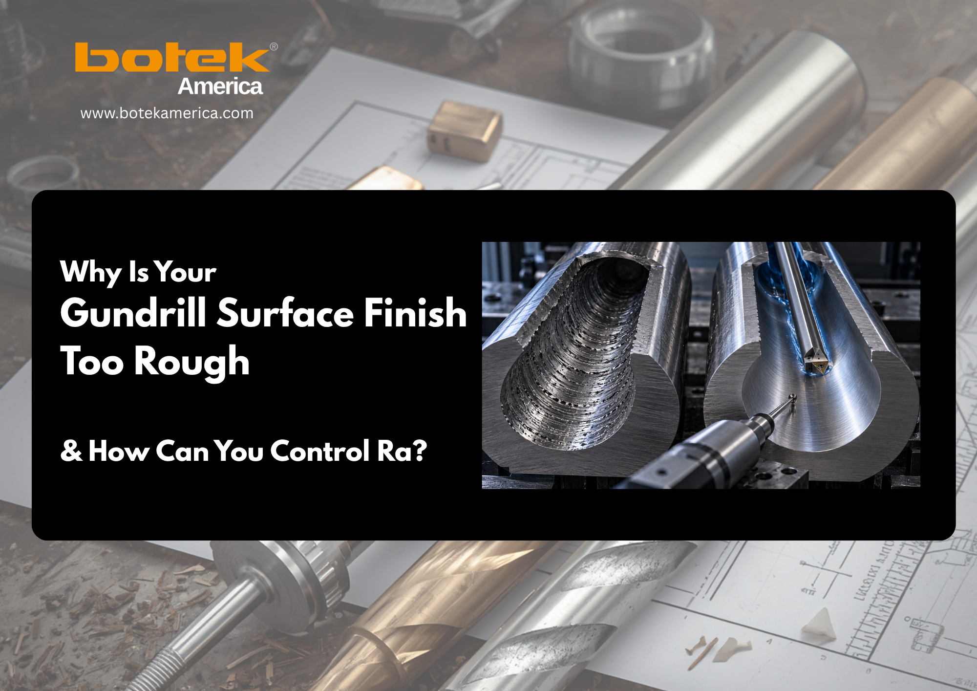
Hitting Ra 0.4 µm consistently requires clean coolant at the correct concentration, a freshly reground edge, guide pads in good condition, and feed rates tuned to the material, all present at once. Titanium and Inconel need significantly lower cutting speeds than steel or aluminum; a process dialed in for 4140 steel typically needs full recalibration before running in Ti-6Al-4V.
Gundrilling vs. Conventional Drilling
| Feature | Gundrill (Single-Flute) | Twist Drill |
| Cutting edges | 1 | 2 |
| Coolant delivery | Internal, high pressure | External, at the surface |
| Chip removal | External V-flute, coolant-swept | Standard flutes, gravity/rotation |
| Depth-to-diameter limit | Up to 400:1 (dedicated machine) | ~5:1 to 8:1 |
| Hole straightness | Maintained by guide pads throughout | Not controlled below shallow depths |
| Surface finish | Ra 0.4–1.6 µm | Typically Ra 3.2–6.3 µm or rougher |
The guide pads are the key difference. A twist drill has no way to stay centered past a short multiple of its diameter; a gundrill carries its own centering mechanism at the cutting head, which is why it holds straightness at depths where a twist drill has already failed.
Single-Flute vs. Twin-Fluted Gundrills
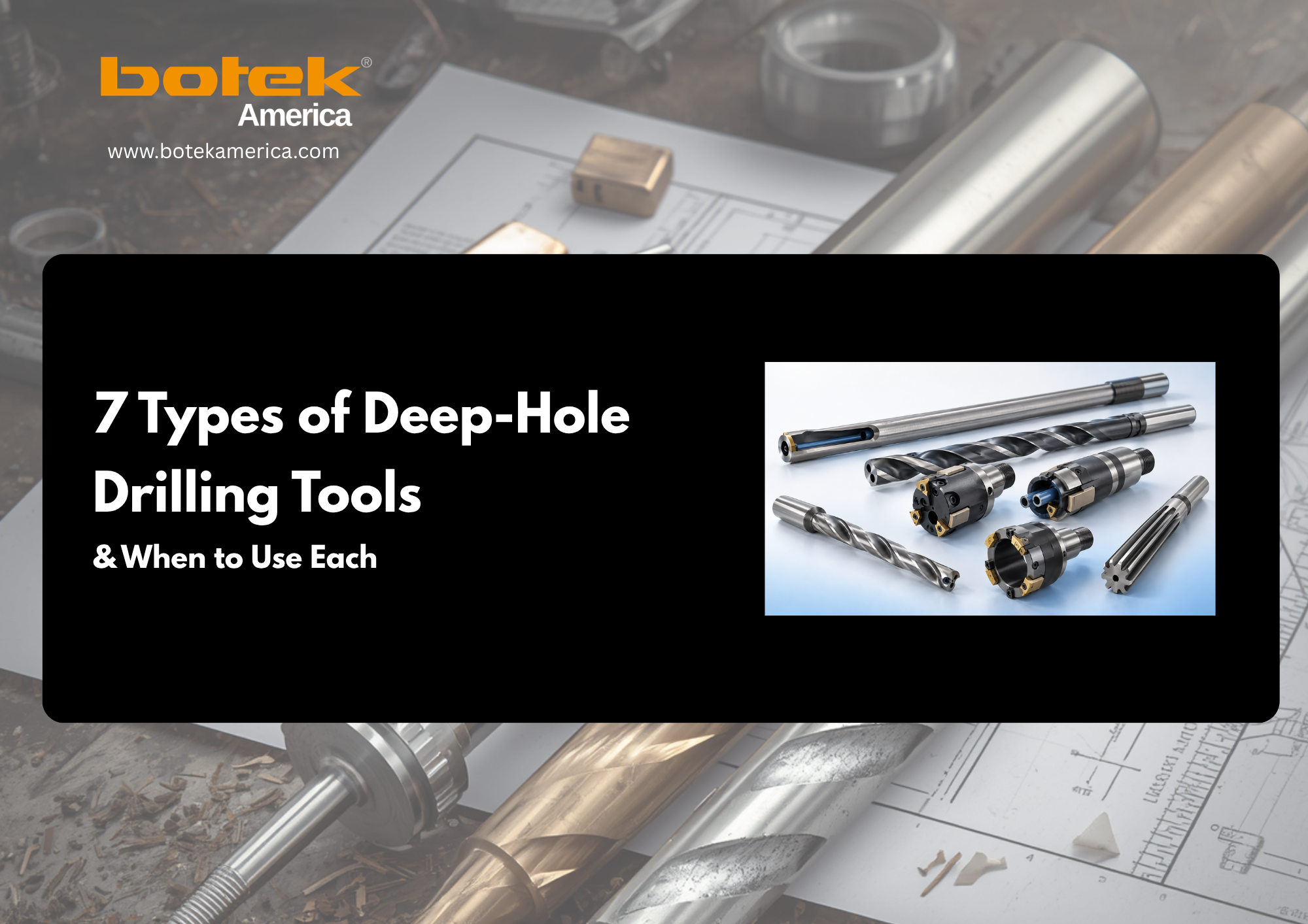
Both are available from Botek, but they’re not interchangeable. Single-flute gundrills cover 0.5–51.2 mm and are the standard choice for deep holes where straightness, finish, and depth-to-diameter ratio matter most. The single edge produces lower cutting forces and gives the guide pads maximum stability. Twin-fluted drills cover 4.5–43 mm, run at higher feed rates, and suit aluminum, cast iron, and shorter, higher-volume jobs, but the increased cutting forces make them unsuitable for extreme depth-to-diameter work. See botek® America’s single-flute gundrill specifications for the full tooling breakdown.
Machine Setup: Dedicated Machine vs. CNC Center
| Consideration | Dedicated Deep Hole Machine | CNC Machining Center |
| Max depth-to-diameter | Up to 400:1 | Up to 20–40:1 (recommended) |
| Coolant pressure available | 200+ bar | 70–100 bar through-spindle |
| Entry guidance | Drill bushing | Pre-drilled pilot hole |
| Best for | Production, deep holes, difficult materials | Prototyping, moderate depths |
A machining center with 70+ bar through-spindle coolant can run gundrills effectively up to roughly 20–40:1, using a pilot hole matched to the drill diameter within close tolerance and at least 2–3 diameters deep. Beyond 40:1, or for difficult materials and high volumes, a dedicated machine delivers stability a machining center can’t match.
Regrinding and Coating
A gundrill’s edge wears with use, and a worn edge means a worse finish, higher cutting forces, and eventually breakage. Set a regrinding schedule based on holes or depth drilled, not visual inspection, since surface finish degradation is the earliest reliable sign a regrind is due. botek® America’s in-house regrinding service restores cutting geometry and guide pad condition at its Roselle, Illinois facility.
Coating is available on new tools only; botek® America doesn’t recoat resharpened tools. TiAlN is standard for steel and cast iron, DLC and uncoated carbide work better for aluminum; and titanium or stainless applications may need specialized coating specified at order time.
Where Gundrilling Is Used
Gundrilling is standard across precision manufacturing: aerospace and defense (landing gear cylinders, hydraulic manifolds, actuator components in titanium and Inconel), medical technology (cannulated implants, surgical instrument channels), automotive and powertrain (crankshaft oil galleries, fuel rails, camshaft passages), mold and die (cooling channels in P20 and H13 tool steels), hydraulics and pneumatics (cylinder bores, manifold drillings), and energy (heat exchanger tube sheets, turbine components). botek® America’s deep hole drilling solutions page breaks down tooling recommendations by industry in more detail.
Gundrilling Process FAQ
What is the depth limit for gundrilling?
Up to 400:1 depth-to-diameter on a dedicated machine. A 5 mm gundrill can reach 2,000 mm deep. On a CNC machining center, the practical limit is 20–40:1, depending on coolant pressure, material, and chip evacuation distance.
Why a single cutting edge instead of two?
Lower cutting forces let the guide pads maintain their stabilizing effect at depth. Two edges increase cutting force and make it harder for the pads to keep the tool centered. For deep, precision holes, single-flute is the correct design.
What happens if coolant pressure drops mid-cycle?
Chip evacuation slows, chips pack in the flute, heat spikes, and the tool seizes and breaks. Stop the cycle immediately if pressure drops unexpectedly.
Can I run a gundrill on my CNC machining center?
Yes, with through-spindle coolant at 70 bar or higher, up to roughly a 20:1 to 40:1 depth-to-diameter ratio with a correctly sized pilot hole. For deeper holes or harder materials, a dedicated machine is the better call.
How often should I regrind?
Set a schedule by holes or depth drilled and watch surface finish as the earliest wear indicator rather than waiting for visible damage.
Work with botek® America’s application engineers.Gundrilling works when tool geometry, coolant strategy, machine setup, and cutting values are all matched to the application. botek® America’s engineers review your material, hole diameter, depth, and tolerance requirements, then help you optimize your drilling process before production starts. Contact an application engineer. |